
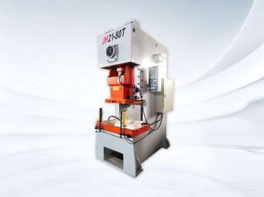
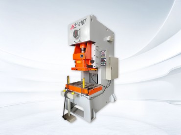
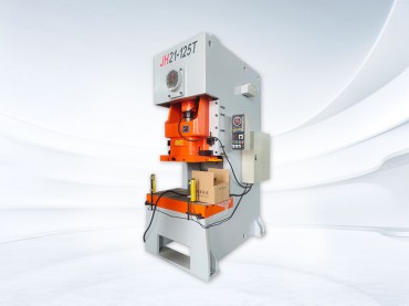
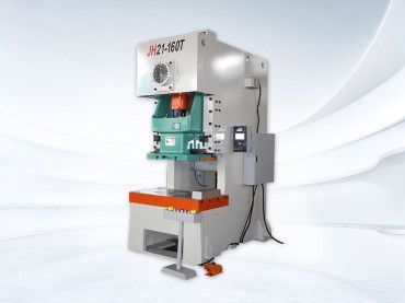


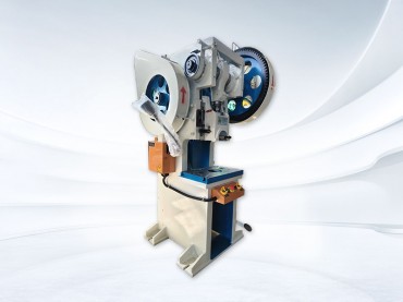
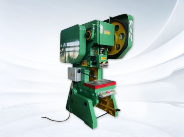
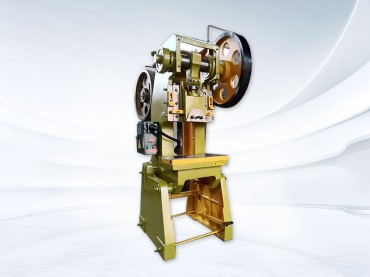
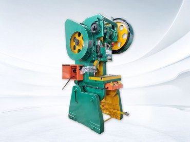
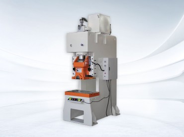
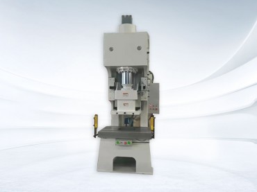

1,Machine model name
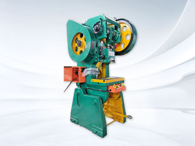
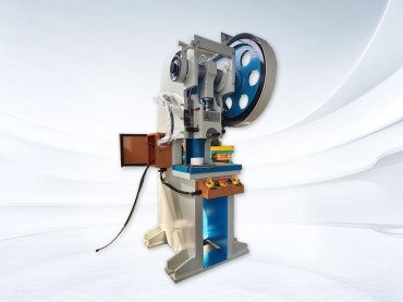
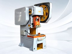
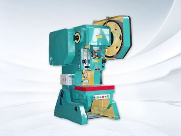
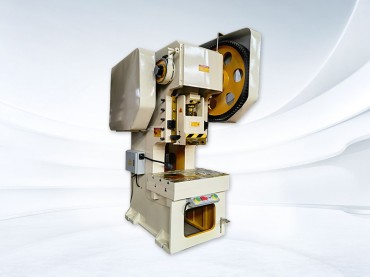
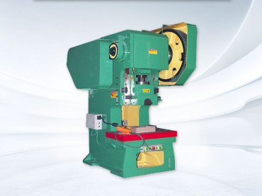
Model: JB23-25T mechanical punching machine

2, Main parameters

3, Structure and performance
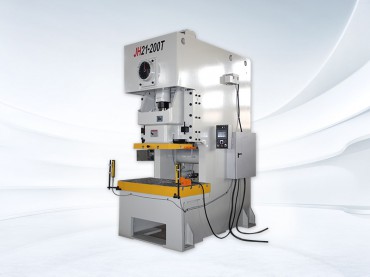
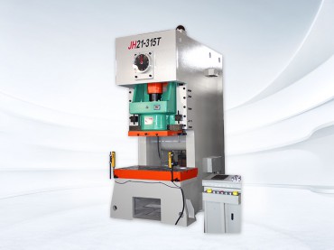
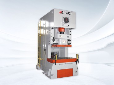
The main components of the punch press are mostly made of high-strength castings, and the whole machine is composed of a body, large gears, pulleys, crankshafts, connecting rods, transmission shafts, clutches, sliders, and other parts. The drive shaft transmits the power of the electric motor to the pulley, and drives the crankshaft to rotate through the clutch of the clutch, thereby causing the slider to move up and down. When it reaches the bottom dead center, it generates the maximum pressure to achieve the stamping of the workpiece. The slider guide rail has been finely ground by a grinder to increase stamping accuracy and improve its service life. The punch press is equipped with a well-known set of electrical appliances and centralized lubrication by an oil pump. The body can tilt backwards for easy material dropping. Optional photoelectric protection device can be installed to make the operation safer and more reliable.
Punching machine is an efficient and low consumption processing equipment that can achieve stamping, forming, cutting, stretching and other processes for metal and non-metal materials. With its unique advantages, it is widely used in mechanical manufacturing industries such as automobiles, aviation, hardware, electrical appliances, and light industry, and occupies an important position.
The main components of this press include: 1. Body 2, transmission 3, clutch 4, slider 5, brake 6, manipulating mechanism. The structure and adjustment instructions of each component are as follows:
3-1. Body
The body is an open double column C-shaped integral cast iron piece, which is placed on the left and right machine legs and firmly connected together with bolts. The lower parts of the two machine legs are fixed together with two tension double headed bolts at the front and back. The left and right machine legs are cast with arc-shaped grooves to allow the body to tilt. There is a rectangular circular feeding hole in the middle of the machine body workbench for dropping out workpieces or waste materials.
The machine body workbench is equipped with a workbench pad that is fastened to the workbench with bolts. The pad pad has T-shaped grooves for installing molds. The left and right guide rails are fastened to the body with screws, and the slider uses the V-shaped groove of the guide rail to ensure the accuracy of its vertical movement. The crankshaft is closed horizontally, and wear-resistant sleeves are installed in the through shaft sleeves on both sides of the machine body. The through shaft sleeves are fixed to the machine body with bolts, and the crankshaft rotates and moves inside the shaft sleeves. There is a control mechanism installed on the right side of the fuselage. On the back of the fuselage, there is a tilt bracket, and rotating the tilt screw can make the fuselage stand upright or tilt, with a maximum tilt angle of 20 °.
3-2. Transmission
The transmission system is powered by an electric motor installed above the rear of the aircraft. The starting of the electric motor is achieved by driving the flywheel through the transmission shaft through a small pulley triangle belt under idle operation, and then driving the large gear through the small gear. The crankshaft is rotated by the clutch mechanism that connects the large gear with the crankshaft, and the slider moves up and down back and forth with the eccentricity of the crankshaft. The motor is fixed on the motor base plate, and is supported on the left and right arch backs of the machine body with the help of connecting bracket joint bolts. The tightness of the V-belt can be adjusted by rotating the nuts on the joint bolts.
3-3. Clutch
The clutch is placed on the right end of the crankshaft. The rotary key of the clutch is a rolling key type. When in the separation position, the operator's contact pressed against the key handle of the rotary key, and the working key was hidden in the rotary key socket of the clutch disc, causing the large gear to idle. When combined, the manipulator rotates to one side under the pull of the foot pedal, and the key handle no longer presses against it. Therefore, the rotary key enters the groove of the joint ring through the action of the tension spring, driving the crankshaft to rotate and achieve stamping. The opening and closing of the work key realizes the disengagement and cooperation of the clutch, thereby controlling the operation of the slider.
3-4. Sliding block
The slider is located between the body rails and moves up and down in a straight line in the V-shaped groove of the rail through the rotational motion of the crankshaft. The connection between the slider and the crankshaft is through a connecting rod mounted on the shaft handle. The connecting rod is connected to the connecting rod screw with threads, and the other end of the connecting rod screw is a ball head type. The ball head is pressed onto the slider through a ball shaped cover. There is a safety block under the ball pad, which collapses to ensure equipment safety when the press is overloaded. The distance between the bottom plane of the slider and the worktable plane can be adjusted by rotating the connecting rod screw to meet the requirements of the mold height. The pressure iron is used to hold the mold handle, and there is a mold handle hole with a diameter of 40 millimeters between the pressure iron and the slider. The slider is equipped with a material return plate. When the slider moves upward, the material return plate touches the material return head installed on the machine body, and the stamped product or waste material falls off from the mold.
3-5. Brake system
The brake wheel is circular and fixed to the left end of the crankshaft with a key, which belongs to continuous braking: the brake belt wrapped around the brake wheel is made of soft steel skin, and the inner surface is riveted with copper wire and asbestos brake belt. One end of the brake band is riveted with a steel plate, which is mounted on the body with a pin shaft, and the other end is riveted with a pull rod. The screw passes through the spring sleeve and is connected together with a nut. A spring is installed on it to adjust the spring tension and generate the required braking torque on the brake, making the slider move smoothly up and down. When the braking force is working normally, the inertia moment generated when the clutch disengages the slider and the crankshaft stops causes the crankshaft to stop within ± 5 degrees of the bottom dead center.
3-6. Manipulating mechanism
This machine tool adopts a foot operated lever control mechanism, which uses a lever to control the up and down movement of the manipulator lever, achieving the engagement and disengagement of the clutch. Thus achieving single or continuous stamping of the slider. The lever and manipulator are installed on the right side of the machine, connected by clamps. When the foot pedal is pressed, the clutch engages and the slider works. After releasing the clutch, the large gear idles and the slider no longer runs downwards. When stamping continuously, simply hold the pedal down and do not release it.
4. Machine tool electrical system
The overview of the electrical control system of this machine is as follows:
Main power supply: 380V, 50Hz, three-phase, control power supply: 220V. The main circuit and motor are both equipped with automatic switches for short-circuit protection and overload protection. The control circuit adopts fuses for short-circuit protection. The main components of the machine are reliably grounded.
5,Working environment and usage conditions
This machine is suitable for any material preparation workshop, with the following conditions:
1. Environmental temperature: -20~+40 ℃
2. Relative humidity: ≤ 80% (+25 ℃)
This machine does not emit any "three wastes" and its noise limit meets the requirements of JB9969-1999.
6, Lubrication system
The lubrication system adopts a manual oil pump centralized oil supply method, and the oil circuit is distributed to each oil supply point through a distributor. The distributor is equipped with a regulating valve, which can adjust the oil supply situation of each oil supply point to ensure sufficient oil supply at each oil supply point. This system has a compact structure, reduces pipeline connections, and improves the lubrication and ease of maintenance of the system.
7,Main configurations


If you need punching machines or are interested in punching machines, please provide the tonnage of punching machines or sheet materials, sheet thickness, sheet width, punching diameter, and we will recommend suitable punching machines for you
 Address:Room 1202, Detaitang Building, No. 118 Huaguang Road, Zhangdian District, Zibo, Shandong
 WhatsApp:+8615653328535
 Wechat: +8615965331535
  E-mail:zs@sdsmachinery.com